MicroSD Pinout A Stepbystep Guide
CMD - A bidirectional pin for communication between the microcontroller and the SD card, used for commands and information. 4 Data pins - Four bidirectional pins for communication between the microcontroller and the SD card, used for transferring bulk data. Take care to wire these in the correct order!
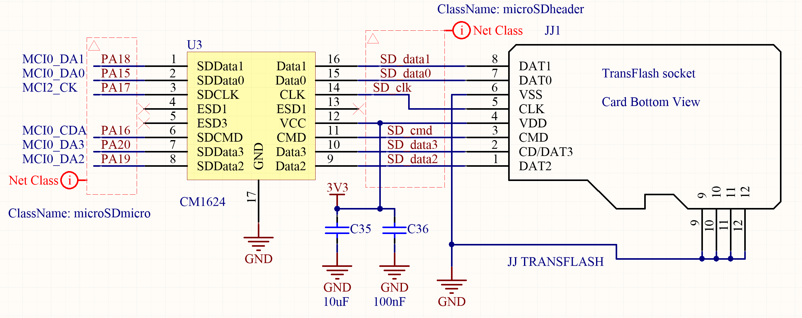
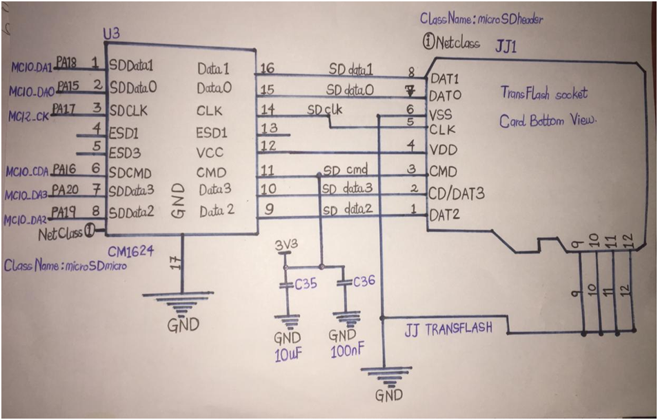
How to design the microSD circuitry
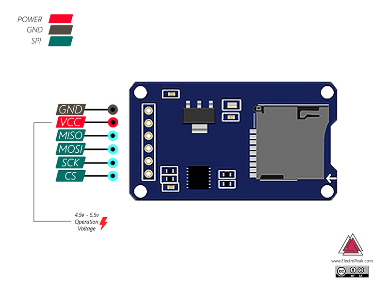
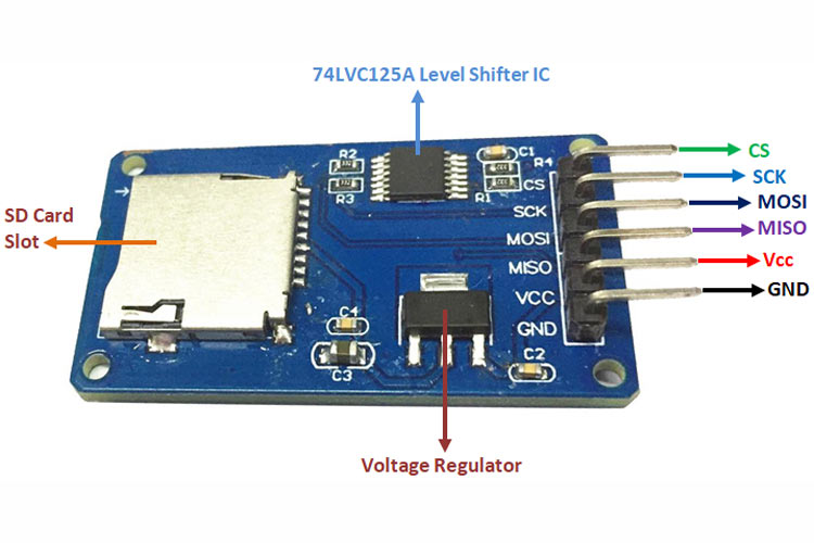
Micro SD Card Module Pinout. The Micro SD Card module has 6 pins; those are GND, VCC, MISO, MOSI, SCK, and CS. All the pins of this sensor module are digital, except VCC and Ground. The Pinout of a Micro SD Card Module is shown below: GND is the ground pin of the micro sd card module and it should be connected to the ground pin of the Arduino.
Micro SD Card Socket Push In Pull Out [6174] Sunrom Electronics
Looking for Sd Card Connector? We have almost everything on eBay. No matter what you love, you'll find it here. Search Sd Card Connector and more.
Arduino SD Card Module How to Read/Write Data StepbyStep Tutorial
SDIO is a multi-pin data protocol (up to 4 data pins at once!) SDIO also tends to be able to be clocked faster than SPI. Of course, your speeds will vary depending on what microcontroller you hook it up to.

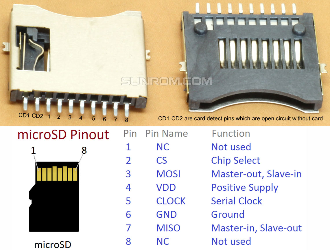
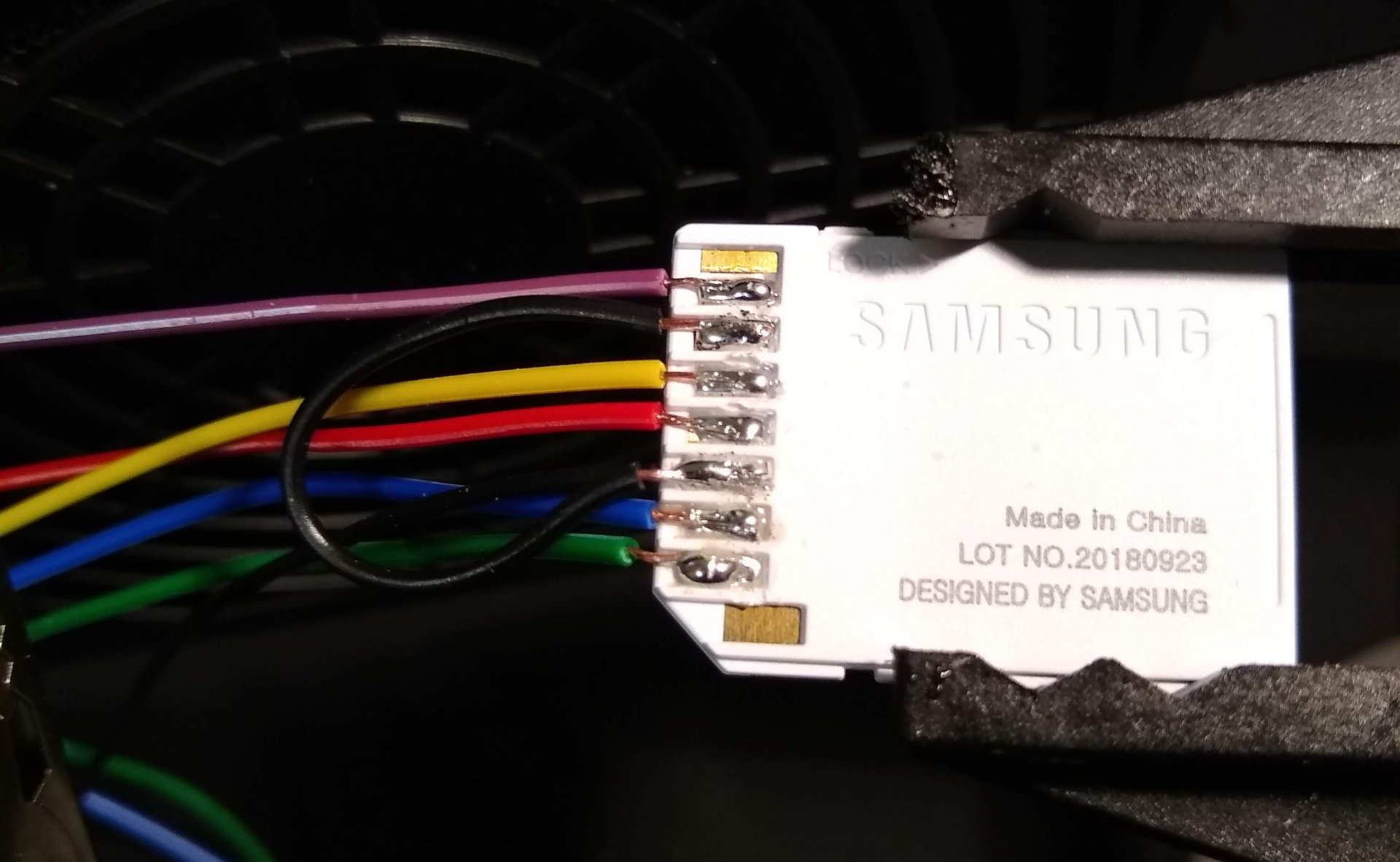
identification Identifying pins on a micro SD card interface on the PCB side Electrical
Favorite 1 Introduction The SparkFun microSD Shield makes it easy to add mass storage to your project. Required Materials 1x SparkFun microSD Shield 1x pack of R3 stackable headers for the shield. 1x microSD card of your choice, up to 32GB, like SparkFun's 8GB card and adapter pack 1x SparkFun RedBoard or Arduino Uno and a USB cable Assembly

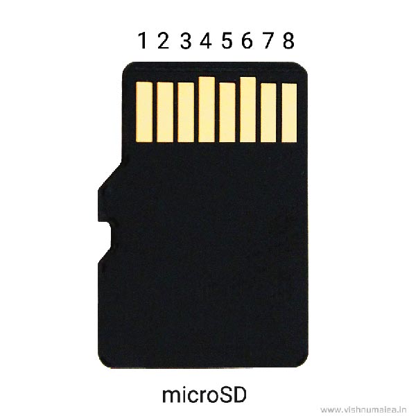
micro sd card pinout
Because SD cards require a lot of data transfer, they will give the best performance when connected up to the hardware SPI pins on a microcontroller. The hardware SPI pins are much faster than 'bit-banging' the interface code using another set of pins.
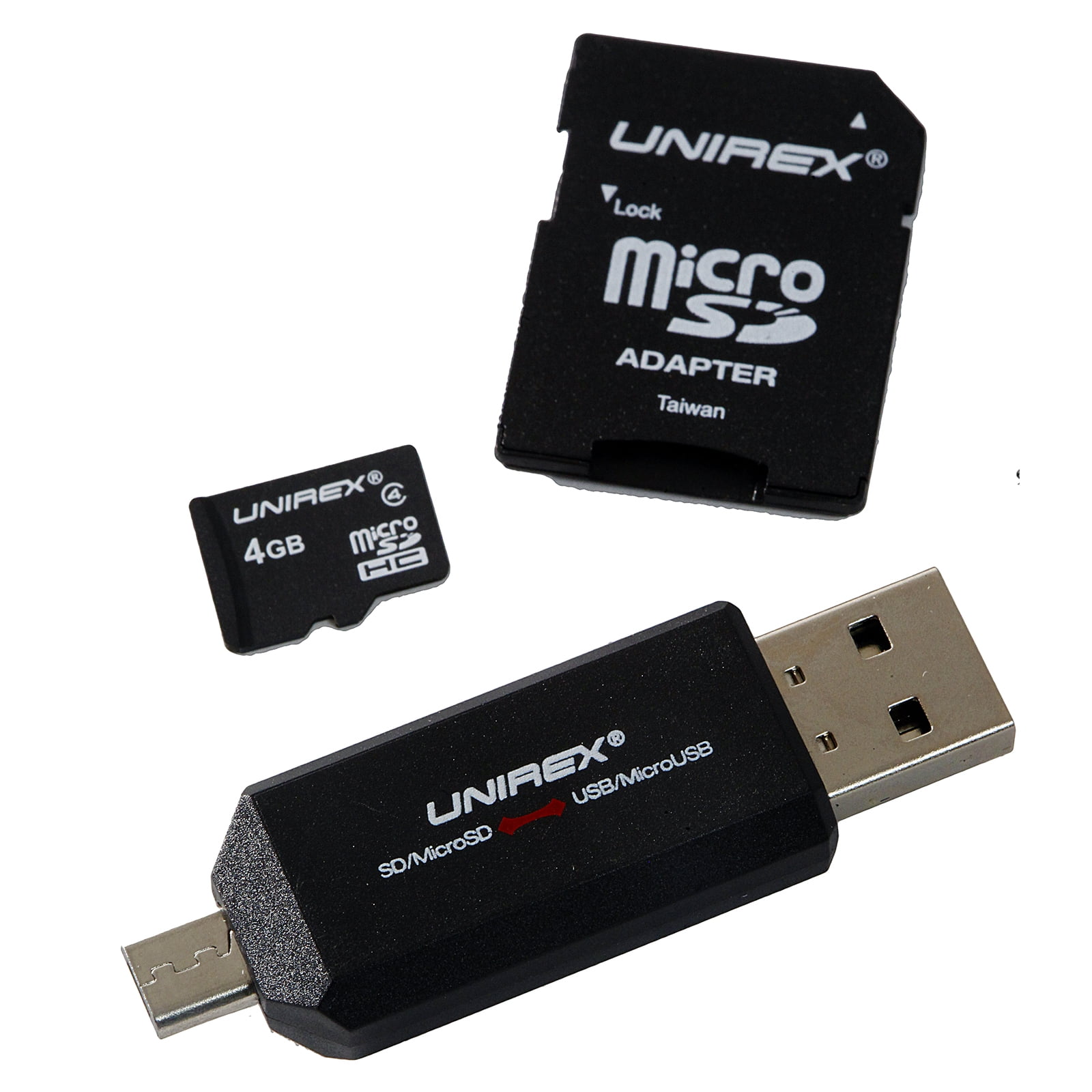
MicroSD 4GB Class 4 w/SD Adapter 4 in 1 Adapter
MicroSD Card Module Pinout The microSD card module is simple to connect. There are six pins on it: VCC pin provides power to the module and should be connected to the Arduino's 5V pin. GND is a ground pin. MISO (Master In Slave Out) is the SPI output from the microSD card module.

Arduino micro SD Card Data Logger
A form factor is the physical size of a part. Comparison of SD Memory Card sizes Including the SD Card, miniSD Card, and microSD Card styles. microSD Card Connector Manufacturers This is a listing of OEM microSD connector manufacturers.
Micro SD Card Adapter Module Pinout, Specifications, Datasheet, Working, Applications, Alternatives
Micro SD Card Adapter Module Pinout. SD cards or Micro SD cards are widely used in various applications, such as data logging, data visualization, and many more. Micro SD Card Adapter modules make it easier for us to access these SD cards with ease. The Micro SD Card Adapter module is an easy-to-use module with an SPI interface and an on-board.
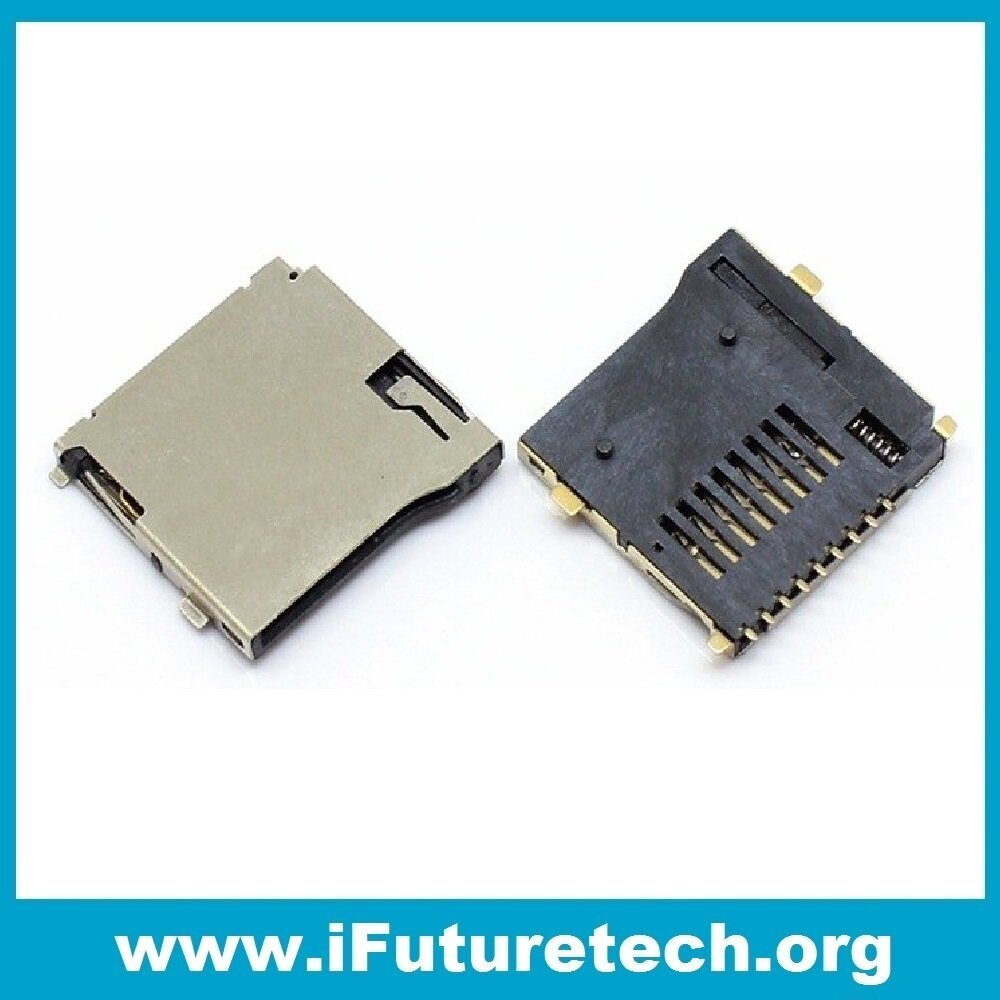
9 PIN MICRO SD CARD SLOT CONNECTORS TF CARD DECK iFuture Technology
Speed class: class 2- class 10 Operating Voltage:2.7V- 3.3V Transfer speed: Averagely 95 MBs per second Storage system: FAT12, FAT16 File system: SDHC/SD/SDXC MicroSD Pinout: Types of Micro SD cards There are three types of Micro SD cards, all having an almost similar physical interface but different memory sizes, namely:
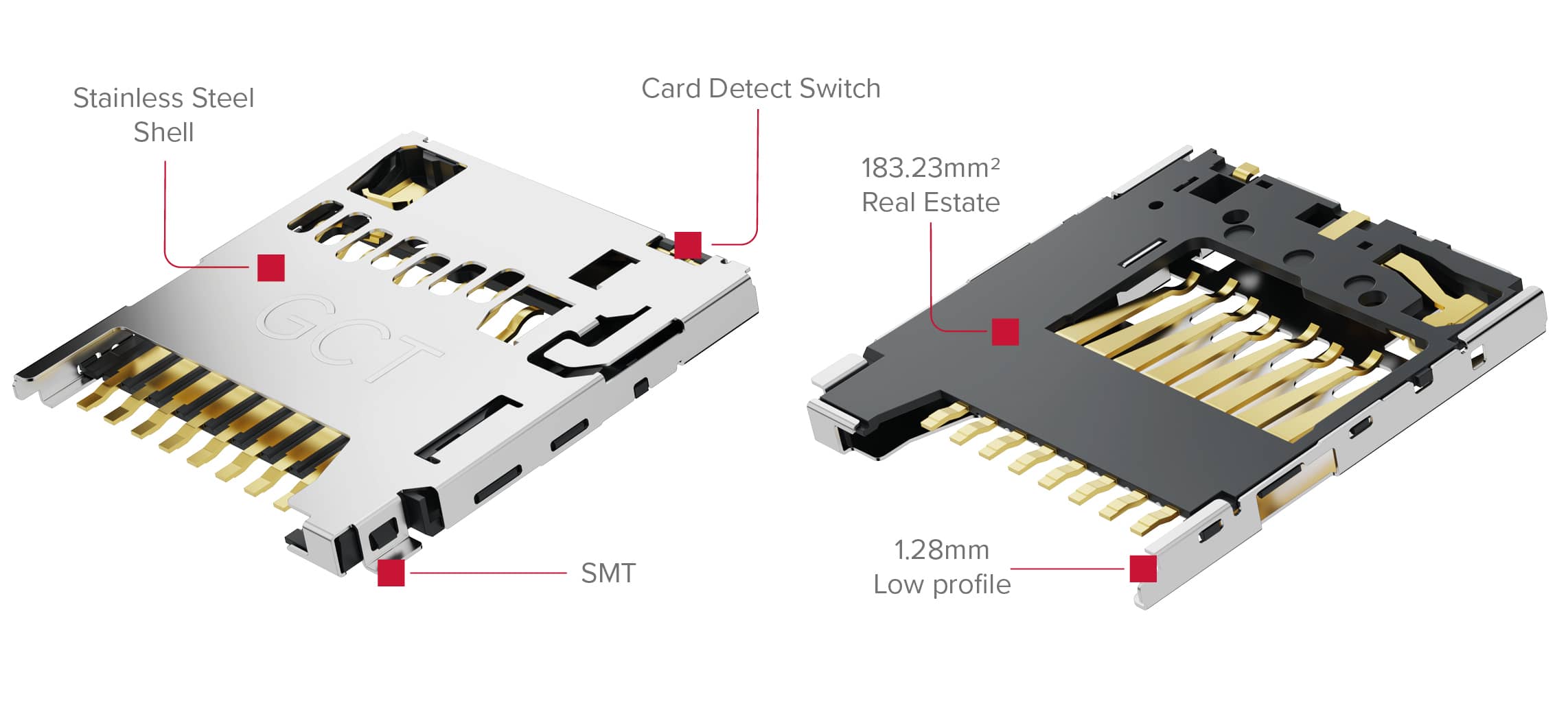
Memory Card Connectors including Micro SD GCT
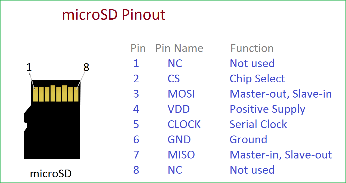
Pinout Circuit Diagram: SD and Micro SD Card pins with description and function. Secure Digital is what SD means, it is a flash based removable memory card. Micro SD Card is a type of Removable small flash memory card format, and has a dimensions of 11mm x 15mm and 1mm thick. Micro SD is short hand for Micro-Secure Digital.
MicroSD Pinout A Stepbystep Guide
Pinout This microSD card module has 6 terminals consisting of SPI and power supply terminals. Below you can view the pinout of this module with some description of the individual pins. Pinout of MicroSD card Module Table showing the pin names and their short descriptions MicroSD card module Interfacing with Arduino Required Hardware:
Connect a microSD card to the ESP8266 or ESP32 using a microSD to SD adapter — Alex Lubbock
The module ( Micro-SD Card Adapter) is a Micro SD card reader module, and the SPI interface via the file system driver, microcontroller system to complete the Micro-SD card. SCK is the SPI bus, CS is the chip select signal pin. 3.3V regulator circuit: LDO regulator output 3.3V as level converter chip, Micro SD card supply. Level conversion.
Module de gestion de cartes MicroSD
Pinout Micro SD Card Module includes 6 pins: VCC pin: connect to the Arduino's 5V pin. GND pin: connect this pin to the Arduino's GND. MISO pin: (Master In Slave Out) connect this pin to the Arduino's MOSI pin. MOSI pin: (Master Out Slave In) connect this pin to the Arduino's MISO pin. SCK pin: connect this pin to the Arduino's SCK pin.

Pin on Electronic components
Parts Required For this tutorial, you need the following parts: ESP32 development board (read: Best ESP32 development boards) MicroSD Card Module MicroSD Card Jumper Wires Breadboard You can use the preceding links or go directly to MakerAdvisor.com/tools to find all the parts for your projects at the best price!
Arduino micro SD Card Data Logger
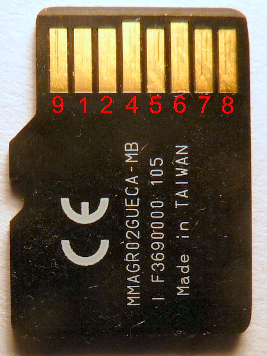
The microSD memory Card has no mechanical write protect switch. 4 Electrical Interface 4.1 Pin Assignment The table below describes the pin assignment of the microSD card. The following figure describes the pin assignment of the microSD card. Please refer to the detail descriptions by SD Card Physical Layer Specification.